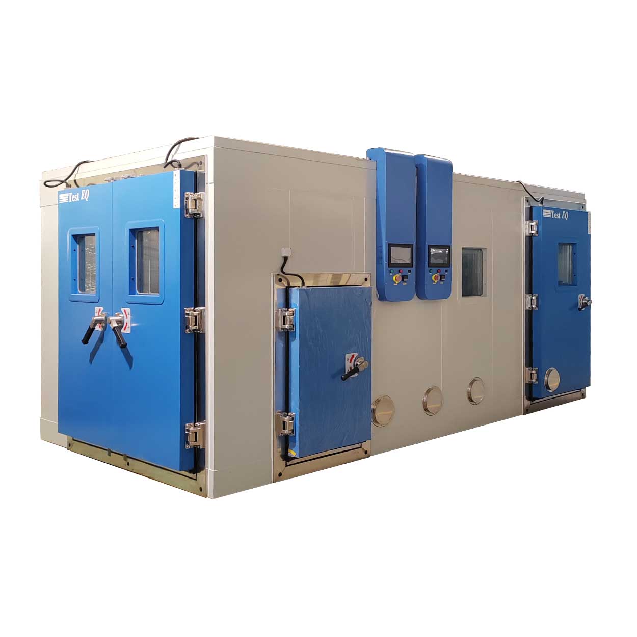
Thermal Cycle Testing for Product Reliability
Thermal cycle testing evaluates how products, components and materials withstand repeated temperature changes during their expected service life.
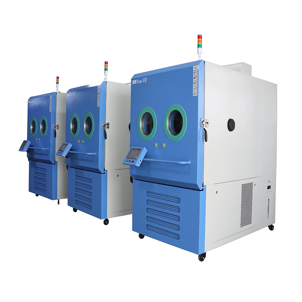
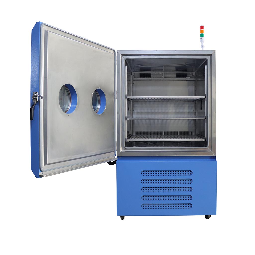
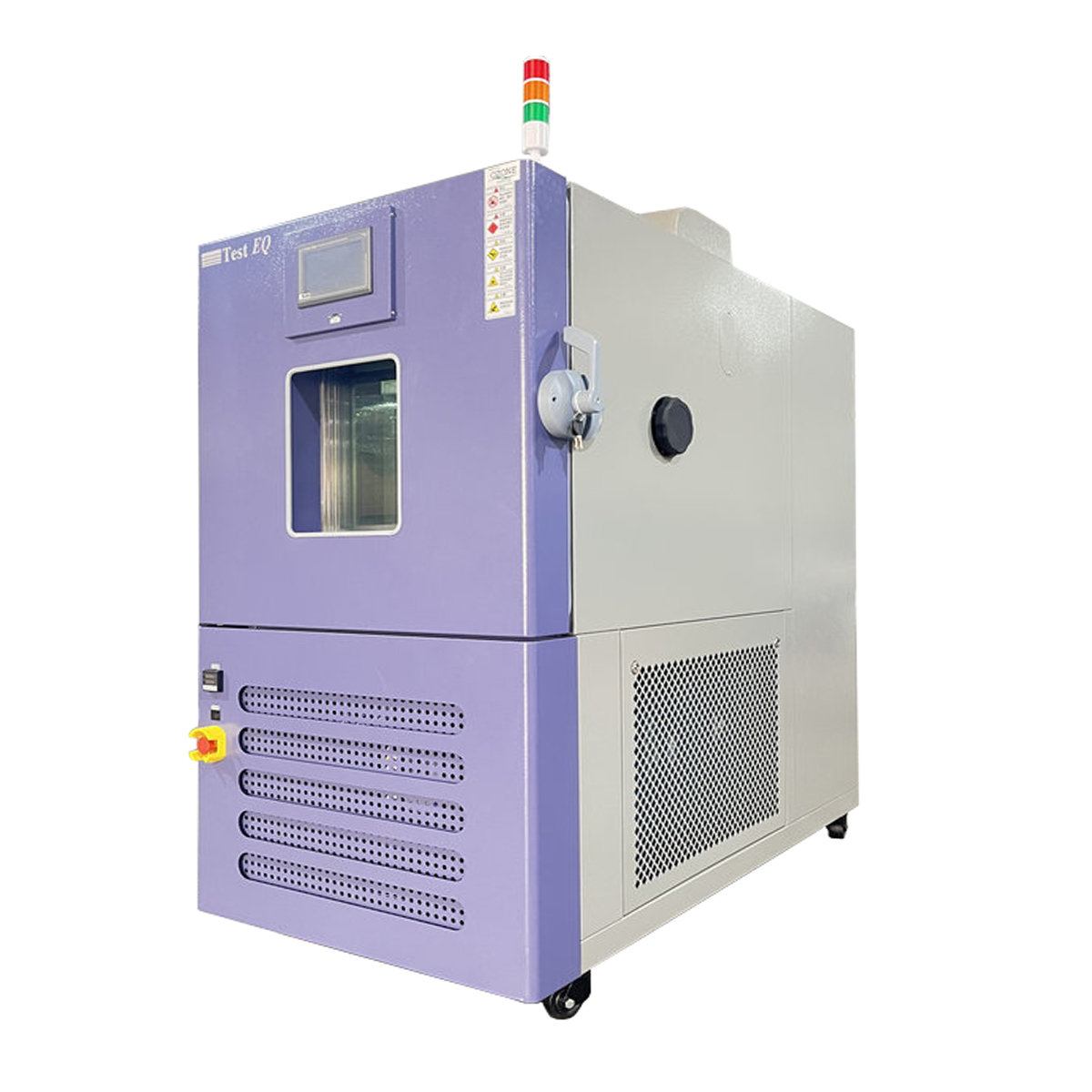
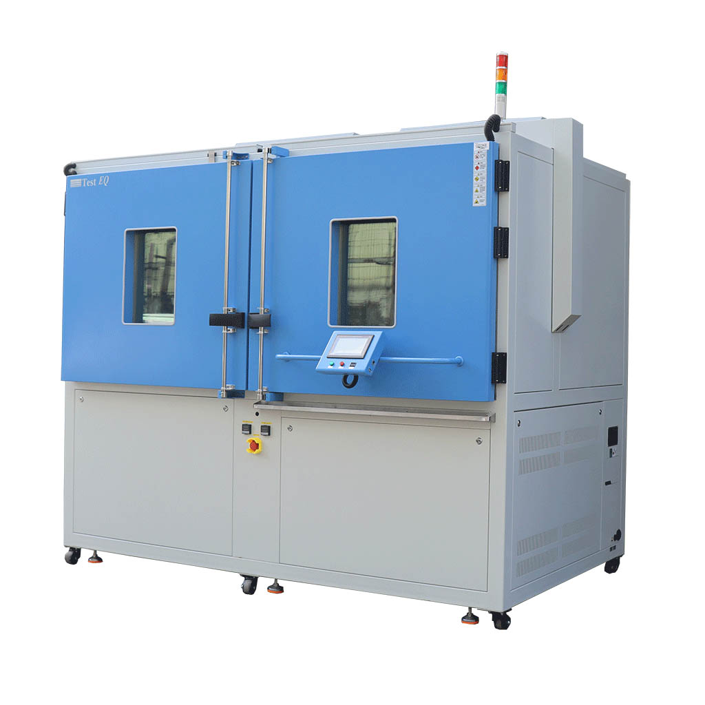
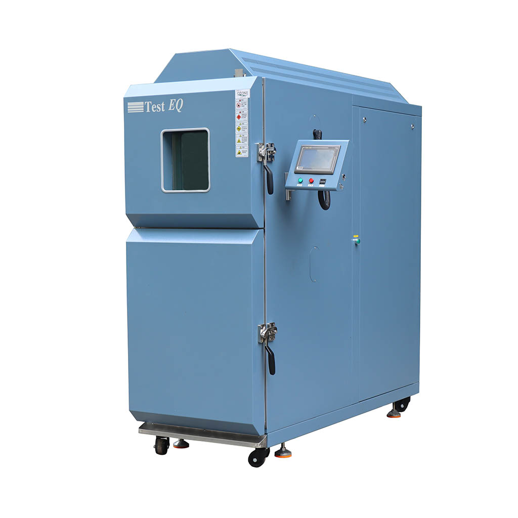
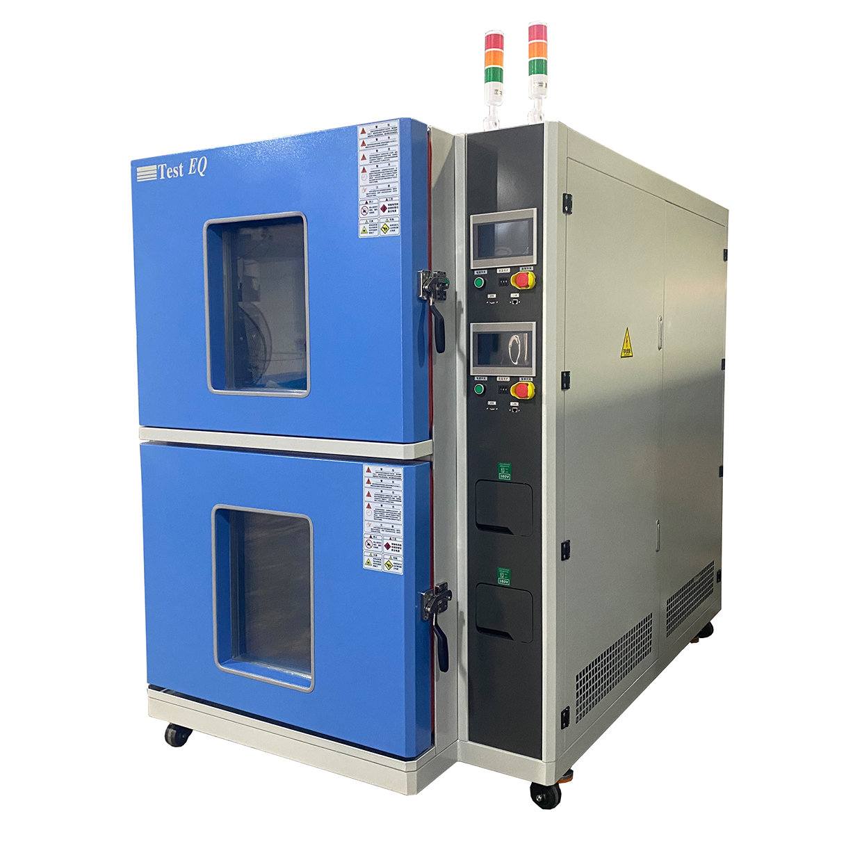
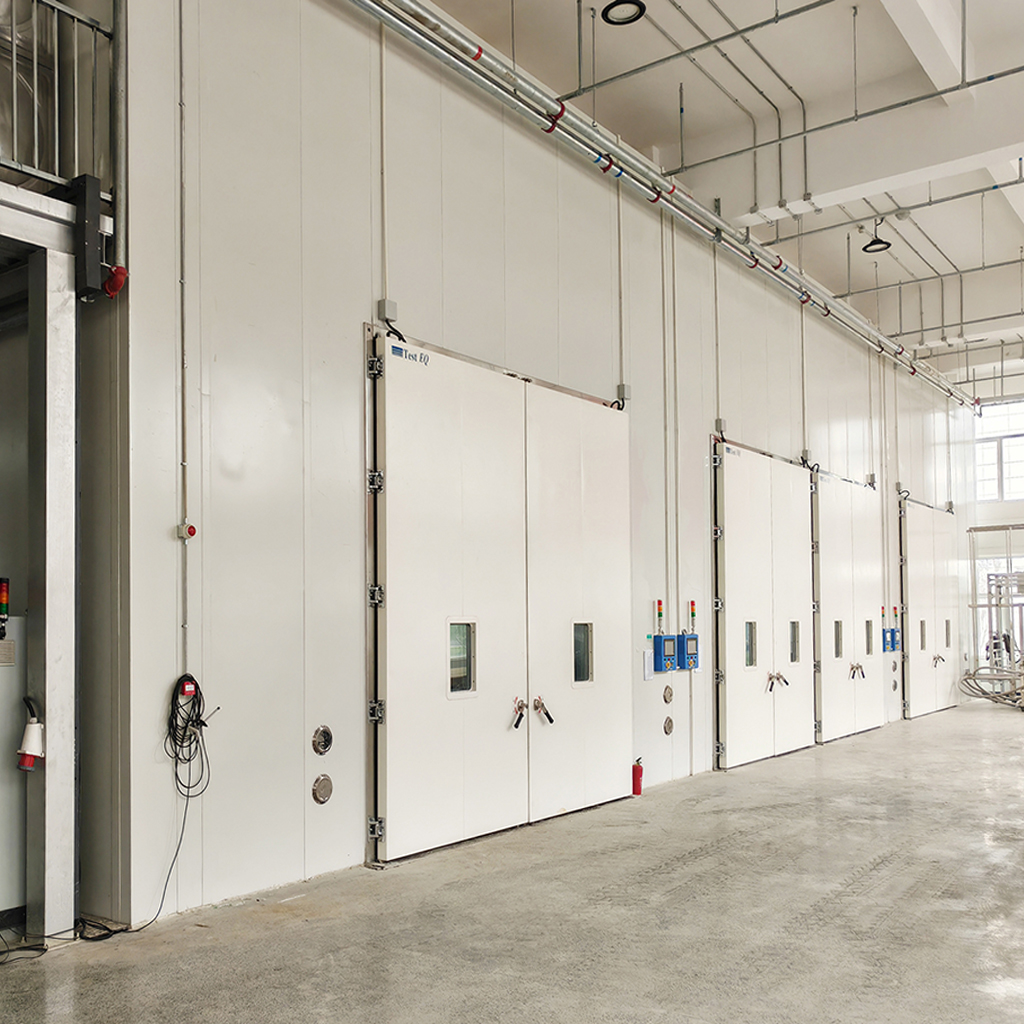
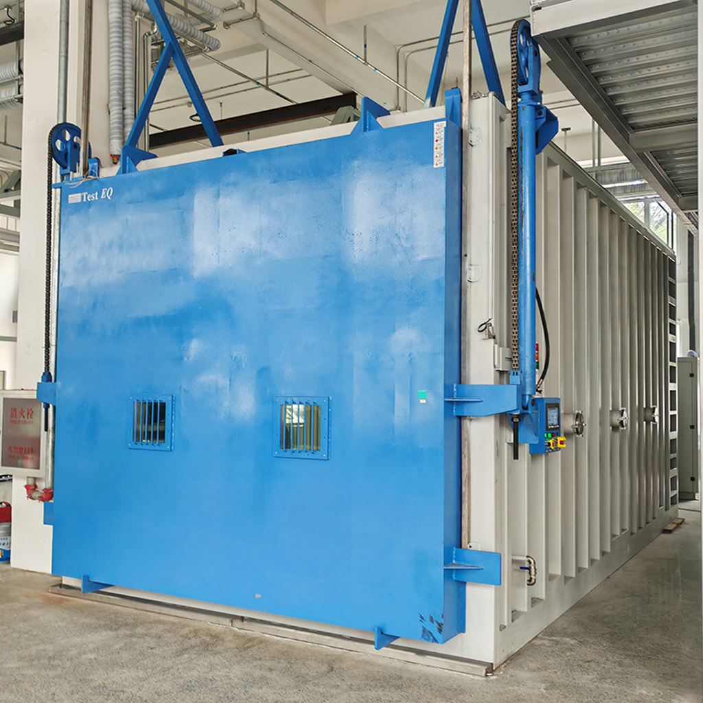
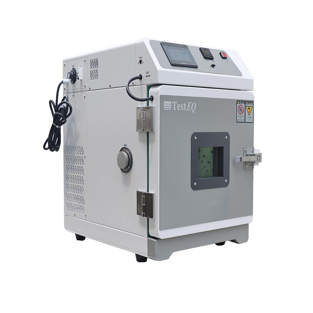
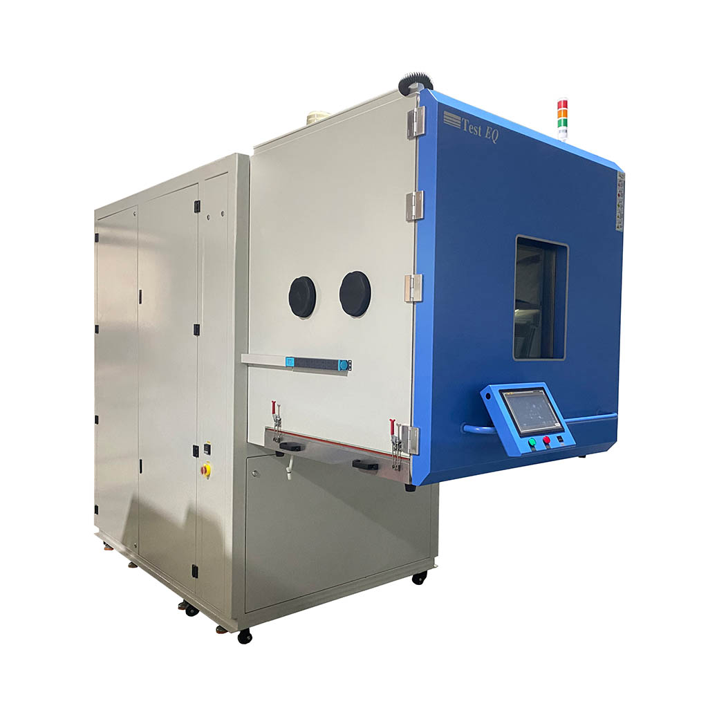
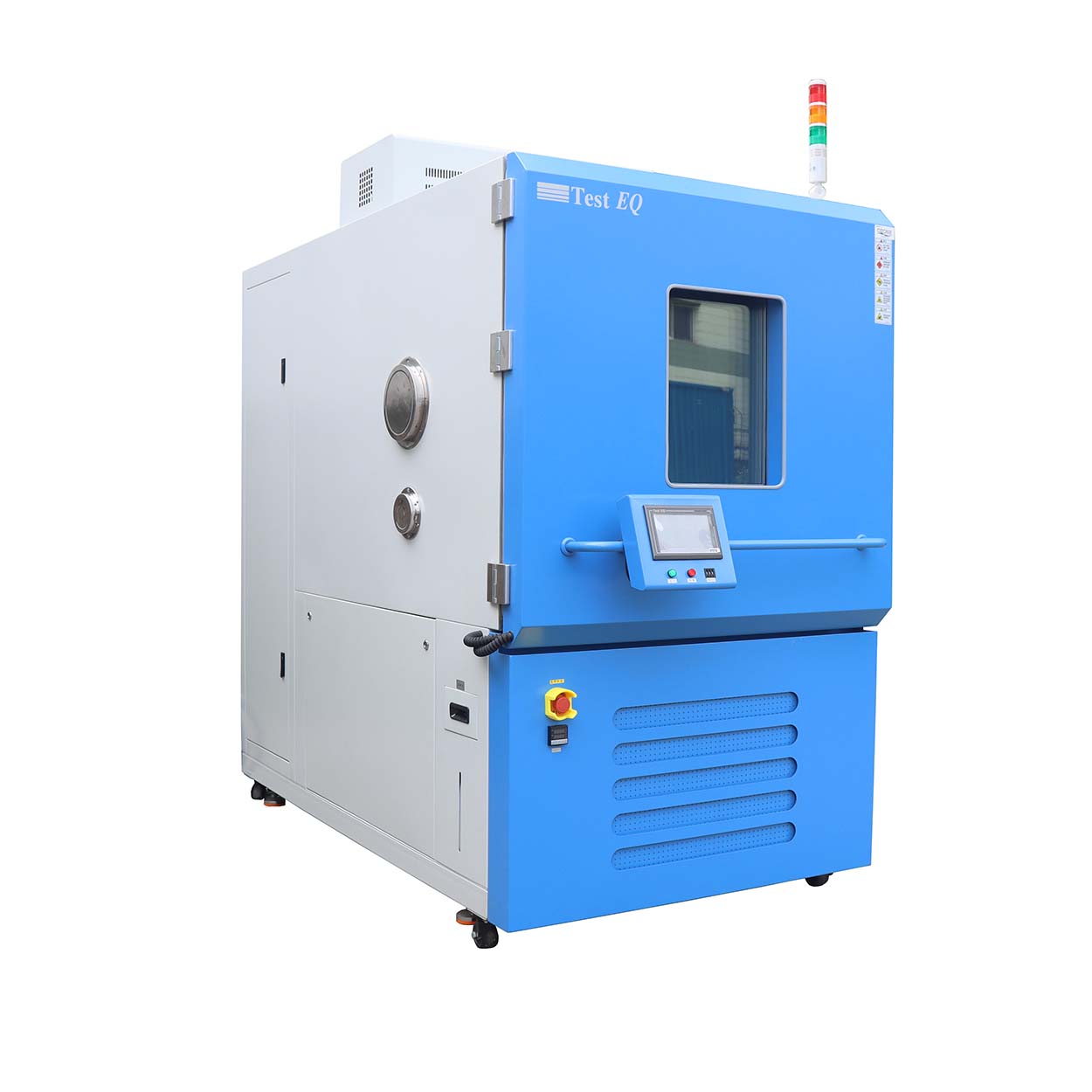
TestEQ provides thermal cycle testing chambers for semiconductor, automotive, EV battery, aerospace and electronics reliability applications. Depending on configuration, systems can provide temperature ranges down to -70°C and controlled linear temperature ramp rates up to 30°C/min.
The test system can be configured around the required temperature profile, specimen load, cycle count, dwell time and applicable reliability standard.
What Is Thermal Cycle Testing?
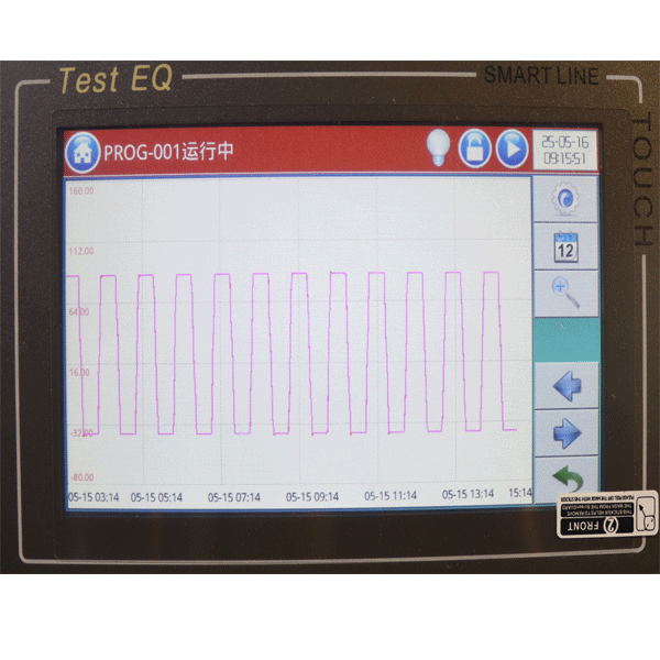
Thermal cycle testing repeatedly exposes a test specimen to defined high- and low-temperature conditions.
A typical thermal cycle consists of:
1. Low-temperature exposure
2. Temperature transition
3. High-temperature exposure
4. High-temperature dwell
5. Temperature transition back to the low condition
6. Repeated cycles
The objective is to reproduce repeated thermal stress that can occur during product operation, transportation or environmental exposure.
Why Perform Thermal Cycle Testing?
Different materials expand and contract at different rates when temperature changes.
This difference in coefficient of thermal expansion (CTE) can create mechanical stress at interfaces and connections.
Repeated temperature cycling can therefore reveal reliability problems such as:
• Solder fatigue
• PCB cracking
• Delamination
• Component package cracking
• Connector degradation
• Wire bond degradation
• Seal and adhesive failure
• Material cracking
• Interconnect fatigue
• Performance drift
Thermal Cycle Testing Parameters
A thermal cycle test should be defined by the complete test profile rather than a single temperature specification.
Important parameters include:
Temperature Range
Define the required high and low temperatures according to the product specification and applicable standard.
Ramp Rate
Ramp rate determines how quickly the chamber moves between temperature conditions.
Typical configurations include:
• 5°C/min
• 10°C/min
• 15°C/min
• 20°C/min
• 25°C/min
• Up to 30°C/min for selected systems
Dwell Time
Dwell time allows the specimen and chamber environment to stabilize before the next transition.
Number of Cycles
Cycle count depends on the applicable qualification specification and reliability objective.
Test Load
Specimen mass and fixture design can affect ramp performance and temperature recovery.
Thermal Cycle Testing Equipment
A thermal cycle test requires more than simply reaching a high and low temperature.
Engineers should evaluate:
For procurement, suppliers should provide performance information under conditions representative of the intended test load.
Typical Failure Modes Found During Thermal Cycling Testing
Thermal cycling testing is primarily used to reveal thermally induced mechanical fatigue and reliability weaknesses that may not appear during static temperature exposure. Repeated temperature transitions cause materials, components, solder joints and interfaces to expand and contract at different rates. Over repeated cycles, these differences can accumulate mechanical stress and eventually produce measurable degradation or failure.
Typical failure modes found during thermal cycling testing include:
1. Solder Joint Fatigue and Cracking
Repeated heating and cooling creates cyclic shear and tensile stress in solder joints because solder, PCB materials and component packages typically have different coefficients of thermal expansion (CTE). Over time, this can cause solder fatigue, crack initiation and crack propagation, leading to intermittent or open electrical connections.
2. PCB Cracking and Delamination
Printed circuit boards can experience repeated mechanical stress as the substrate expands and contracts during temperature transitions. Thermal cycling may reveal cracks in PCB structures, layer separation, or delamination between different material interfaces.
3. Component Package Cracking
Semiconductor packages and other electronic components can develop mechanical cracks when their internal materials experience repeated thermal expansion and contraction. Package cracking can compromise electrical performance, moisture resistance and long-term reliability.
4. CTE Mismatch Failures
A significant failure mechanism is the difference in coefficient of thermal expansion between joined materials. Examples include silicon, solder, copper, PCB laminate, ceramics, polymers and metal housings. Repeated temperature cycling amplifies the resulting mechanical stress at interfaces and joints.
5. Delamination and Interface Separation
Repeated thermal stress can weaken adhesive layers and material interfaces. Delamination may occur between encapsulants, substrates, coatings, laminates or other bonded structures, potentially creating pathways for moisture ingress or further mechanical damage.
6. Wire Bond and Interconnect Degradation
In semiconductor and electronic assemblies, repeated thermal expansion and contraction can stress wire bonds, lead frames and other interconnect structures. This may result in bond degradation, cracking, increased electrical resistance or intermittent connectivity.
7. Connector and Contact Failure
Connectors and electrical contacts can experience repeated mechanical movement caused by thermal expansion differences. Thermal cycling may lead to contact degradation, intermittent connections, increased contact resistance or mechanical loosening.
8. Seal, Gasket and Housing Failure
Temperature changes can repeatedly expand and contract seals, gaskets and enclosure materials. After sufficient cycles, this may result in loss of sealing performance, deformation, cracking or reduced environmental protection.
Thermal Cycling Chamber vs Thermal Shock Chamber
| Comparison Factor | Thermal Cycling | Thermal Shock |
|---|
| Primary Purpose | Evaluates long-term thermal fatigue, durability, and reliability under repeated temperature changes | Evaluates resistance to severe thermal stress caused by rapid temperature transitions |
| Main Stress Mechanism | Repeated thermal expansion and contraction over multiple cycles | Sudden thermal gradients and rapid temperature changes |
| Temperature Transition | Controlled and relatively gradual | Very rapid, often involving direct transfer between hot and cold zones |
| Typical Equipment | Thermal Cycling Chamber / Thermal Cycling Test Chamber | Thermal Shock Chamber |
| Specimen Movement | Specimen normally remains in the same chamber | Specimen is typically transferred between hot and cold zones |
| Ramp Rate | Commonly controlled at a specified rate, such as 5–30°C/min | Extremely rapid transition between temperature zones |
| Temperature Profile | Heating → Dwell → Cooling → Dwell → Repeat | Hot Zone → Cold Zone → Hot Zone → Repeat |
| Test Duration | Generally longer because many controlled cycles are performed | Often shorter per cycle because the temperature transition is much faster |
| Typical Failure Mechanisms | Solder fatigue, CTE mismatch, interconnect fatigue, delamination, material degradation | Cracking, delamination, seal failure, solder cracking, material fracture caused by thermal shock |
| Typical Applications | Semiconductor packages, PCBs, automotive electronics, EV components, aerospace components | Electronic components, semiconductor packages, connectors, seals, materials, automotive components |
| Typical Standards | IEC 60068-2-14, JESD22-A104, AEC-Q100, ISO 16750 | IEC 60068-2-14, MIL-STD-810, JESD22 and applicable product standards |
| Best Used When | The objective is to evaluate reliability over repeated thermal exposure and thermal fatigue | The objective is to evaluate resistance to sudden and severe temperature changes |
| Typical Procurement Consideration | Temperature range, ramp rate, cycle count, dwell time, temperature uniformity, specimen load | Hot/cold zone temperatures, transfer time, recovery time, zone volume, specimen load |
| Recommended Equipment | Thermal Cycling Chamber | Thermal Shock Chamber |
Engineering Takeaway:
Thermal cycling and thermal shock are not interchangeable tests.
Thermal cycling focuses on repeated, controlled temperature changes and long-term thermal fatigue.
Thermal shock focuses on rapid temperature transitions and severe thermal gradients.
If the qualification program requires a controlled ramp rate such as 10, 15, 20, or 30°C/min, a thermal cycling chamber is generally the more appropriate equipment category.
If the test requires rapid transfer between hot and cold zones with minimal transition time, a thermal shock chamber is generally more appropriate.
How to Select Thermal Cycle Testing Equipment
Before purchasing equipment, define:
1. High temperature
2. Low temperature
3. Ramp rate
4. Chamber volume
5. Specimen dimensions
6. Specimen weight
7. Cycle count
8. Dwell time
9. Test profile
10. Applicable standard
11. Fixture requirements
12. Monitoring requirements
A chamber should be selected based on the complete test requirement rather than maximum temperature range alone.
Why Choose TestEQ for Thermal Cycle Testing?
TestEQ provides environmental simulation systems for reliability testing and qualification applications.
The engineering team can configure thermal cycle testing systems according to:
• Temperature range
• Ramp rate
• Working volume
• Specimen load
• Thermal cycling profile
• Fixture requirements
• Monitoring requirements
• Applicable standard
Optional Configurations:
• Extended ramp rate (up to 30°C/min or higher)
• Multi-zone temperature control
• Remote monitoring & IoT integration
• Liquid nitrogen cooling system (LN2 boost)
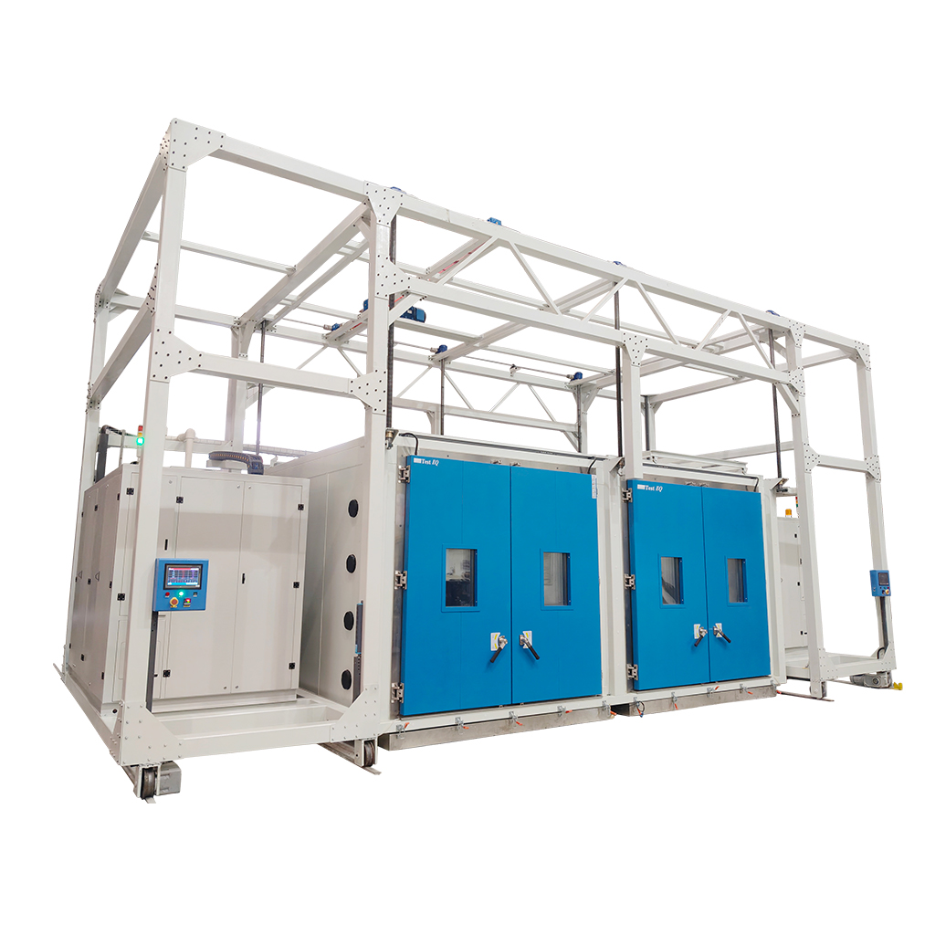
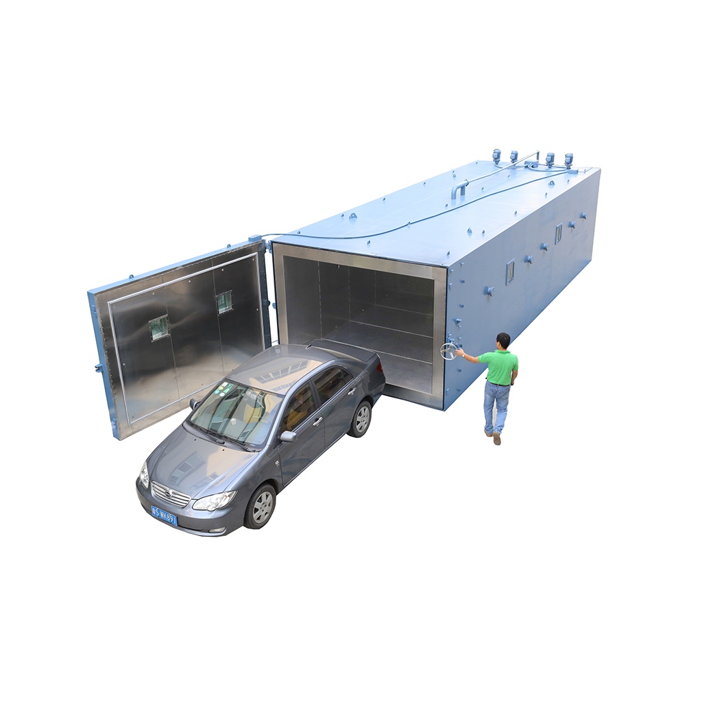
• Large-volume customized chambers
Related Testing Standards
Thermal cycle testing may be associated with:
IEC 60068-2-14 – Environmental Testing: Temperature Change
IEC 60068-2-14 specifies test methods for evaluating a product's ability to withstand rapid and gradual temperature changes. It is widely used for electronic components, industrial equipment, and consumer products to assess reliability under thermal stress.
JEDEC JESD22-A104 – Temperature Cycling Test
JEDEC JESD22-A104 defines temperature cycling procedures for semiconductor devices. The standard is commonly used to identify solder joint fatigue, package cracking, wire bond failure, and other reliability issues caused by repeated thermal expansion and contraction.
MIL-STD-810H – Environmental Engineering Considerations and Laboratory Tests
MIL-STD-810H establishes environmental test methods for military and aerospace equipment. Its temperature cycling procedures verify that products can maintain performance after exposure to repeated extreme temperature conditions.
AEC-Q100 – Stress Test Qualification for Integrated Circuits
AEC-Q100 specifies reliability qualification requirements for automotive integrated circuits. Temperature cycling is one of the mandatory stress tests used to ensure electronic components can withstand long-term operation in harsh automotive environments.
ISO 16750 – Environmental Conditions and Testing for Road Vehicles
ISO 16750 defines environmental testing requirements for electrical and electronic equipment installed in road vehicles. Thermal cycling tests simulate real-world operating conditions to evaluate component durability, reliability, and service life.
RTCA DO-160 – Environmental Conditions and Test Procedures for Airborne Equipment
RTCA DO-160 provides environmental qualification requirements for airborne electronic equipment used in commercial and military aircraft. Temperature cycling tests help verify reliable operation under rapidly changing altitude and temperature conditions.
Why These Standards Matter
Modern thermal cycling chambers should support multiple international standards to meet the testing requirements of different industries. TestEQ Thermal Cycling Chambers are designed to perform reliable temperature cycling tests in accordance with IEC, JEDEC, MIL-STD, AEC, ISO, and RTCA standards, making them suitable for semiconductor, automotive, aerospace, defense, and electronics reliability testing.
FAQ
1.What is a thermal cycling chamber?
Thermal cycle testing repeatedly exposes a product or component to defined temperature conditions to evaluate thermal fatigue, durability and reliability.
2.What failures can thermal cycling detect?
Thermal cycling can reveal solder fatigue, cracking, delamination, CTE mismatch, connector degradation and other temperature-related reliability failures.
3.What is the difference between thermal cycling and thermal shock?
Thermal cycling uses controlled temperature transitions, while thermal shock rapidly transfers a specimen between separate hot and cold zones.
4.What ramp rate is required for semiconductor testing?
Typically, semiconductor testing requires ramp rates between 10–30°C/min, depending on JEDEC standards and test objectives.
5.What standards does this chamber comply with?
This chamber supports MIL-STD-810, IEC 60068, JESD22, and other international reliability testing standards.
6.How to choose a thermal cycling chamber?
Key factors include temperature range, ramp rate, chamber size, uniformity, and compliance standards based on your application.
7.What ramp rate is required?
The required ramp rate depends on the test method. TestEQ systems can be configured for ramp rates from approximately 5°C/min to 30°C/min.
8. How many thermal cycles are typically required for reliability testing?
The required number of thermal cycles depends on the applicable standard and product reliability goals. Common test programs range from 100 to 2,000 cycles, while highly accelerated qualification tests may require even more cycles according to JEDEC, IEC, or customer-specific specifications.
9. Which industries commonly use thermal cycling chambers?
Thermal cycling chambers are widely used in semiconductor, automotive electronics, aerospace, EV battery, telecommunications, medical devices, and consumer electronics industries. They help evaluate solder joint reliability, material durability, electronic component performance, and product lifetime under repeated temperature changes.
10. Can a thermal cycling chamber be customized for specific testing requirements?
Yes. TestEQ thermal cycling chambers can be customized with different temperature ranges, ramp rates, chamber volumes, cooling systems, fixture designs, and automation features to meet specific testing standards and customer applications.
Internal Linking Module
Recommended Equipment
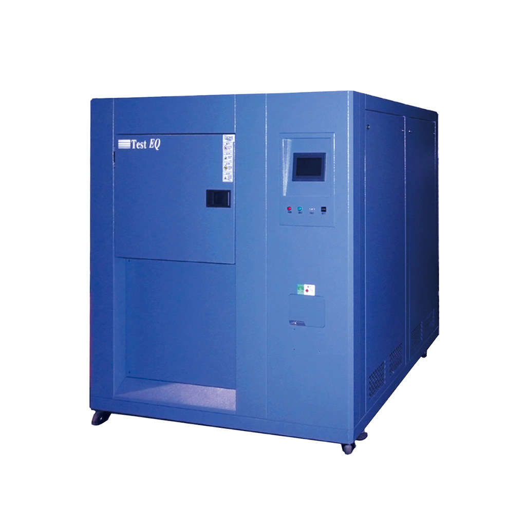
Designed for extreme temperature transition testing between hot and cold zones. Ideal for semiconductor packages, automotive electronics, aerospace components, and reliability qualification programs requiring rapid thermal stress evaluation. Supports IEC 60068, JESD22, and MIL-STD testing requirements.
Engineered for Environmental Stress Screening (ESS) applications with rapid temperature ramp rates and long-duration reliability testing capabilities. Commonly used in automotive, electronics, defense, and aerospace manufacturing environments.
Related Testing Standards
Learn the JEDEC JESD22-A104 thermal cycling methodology for semiconductor reliability qualification, including temperature profiles, cycle counts, failure mechanisms, and industry acceptance criteria.
Overview of IEC 60068 environmental testing requirements covering temperature cycling, thermal shock procedures, environmental stress evaluation, and product durability verification for electronic and industrial equipment.
Reliability Testing Resources
Compare HALT and Thermal Cycling testing methods, understand failure discovery mechanisms, acceleration principles, and selection criteria for product reliability improvement programs.
Understand the differences between thermal cycling and thermal shock testing, including transition rates, stress mechanisms, applicable standards, and recommended use cases for electronics, automotive, and aerospace industries.